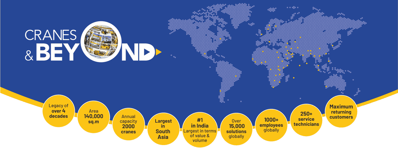
Ranked as Asia's leading manufacturer of industrial overhead cranes and voted as a 'Great Place To Work' for four consecutive years, ElectroMech, with its solutions-driven and result-oriented approach, has addressed the material handling challenges faced by the clients from diverse complexities across varied industries and sectors globally. Our journey toward becoming the leading global material handling solutions provider began four decades ago. Over the years, we have supplied over 10,000 solutions to over 60 countries around the globe. Many years of hardships of our workforce and learning are reflected in our authentic methods to build the solutions that deliver optimum performance and has earned the reputation of being the most comprehensive material handling solutions. We are proud to say that we have 60% of the repeat customers. Our diligent commitment to trust, ownership, customer focus and growth make us the most reliable material handling partner for your next project
We have efficiently scaled up our manufacturing plans from time to time and built a tradition characterized by workmanship, constant innovation, and optimization of industrial processes. Currently, we have a manufacturing plant in India, Dubai, Indonesia & Saudi Arabia. Our manufacturing facility has an annual capacity of 2000 standard cranes and is equipped with workstations that can accommodate multiple cranes simultaneously. We have provided ergonomically crafted designs for arduous conditions to various industries and sectors globally. Our efforts to establish ourselves as a prominent player in the material handling solutions industry have empowered us to develop our skillsets and acumen for delivering solutions to various industries across diverse geographical locations and complexities. Our workforce is equipped with years of on-field knowledge and constantly shares their ideas to improve and optimize our work processes to deliver the best to our clients
Our motto "Where there is a problem, there is a solution" has allowed us to work and resolve material handling problems faced by a diverse range of customers across varied industries and sectors. This diverse experience has helped us gain insights into the core operations of different sectors and their challenges. This understanding propels us towards continuous growth and developing new customized ways of solving our customer's unique problems
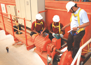
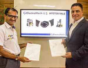
We don't just stop at crane manufacturing and supplying – we go “Cranes & Beyond”. Over the past four decades, ElectroMech has earned a reputation not only as a leading industrial crane manufacturer and supplier but also as a material handling solutions provider to a host of other different applications and industries. By joining hands with the global leaders in the material handling domain, ElectroMech has become a One-Stop-Shop and can efficiently address various challenges through its wide range of industry-leading solutions. We have earned the trust of our customers by going the extra mile and ensuring our unmatched services throughout the life cycle of your equipment through our service partner - Cranedge. Cranedge ensures efficient services and assures a resolution commitment of 48 hours to our customers - #AnyMake #AnyWhere. Their ability to diagnose problems, well-laid processes, technical expertise, excellent logistics, and healthy spare inventory all ensure the highest uptime of your material handling equipment.
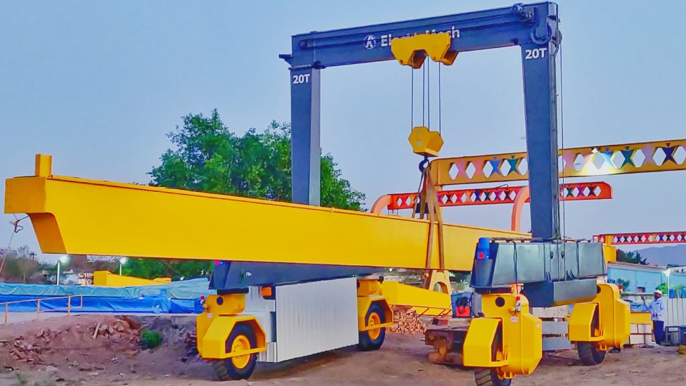
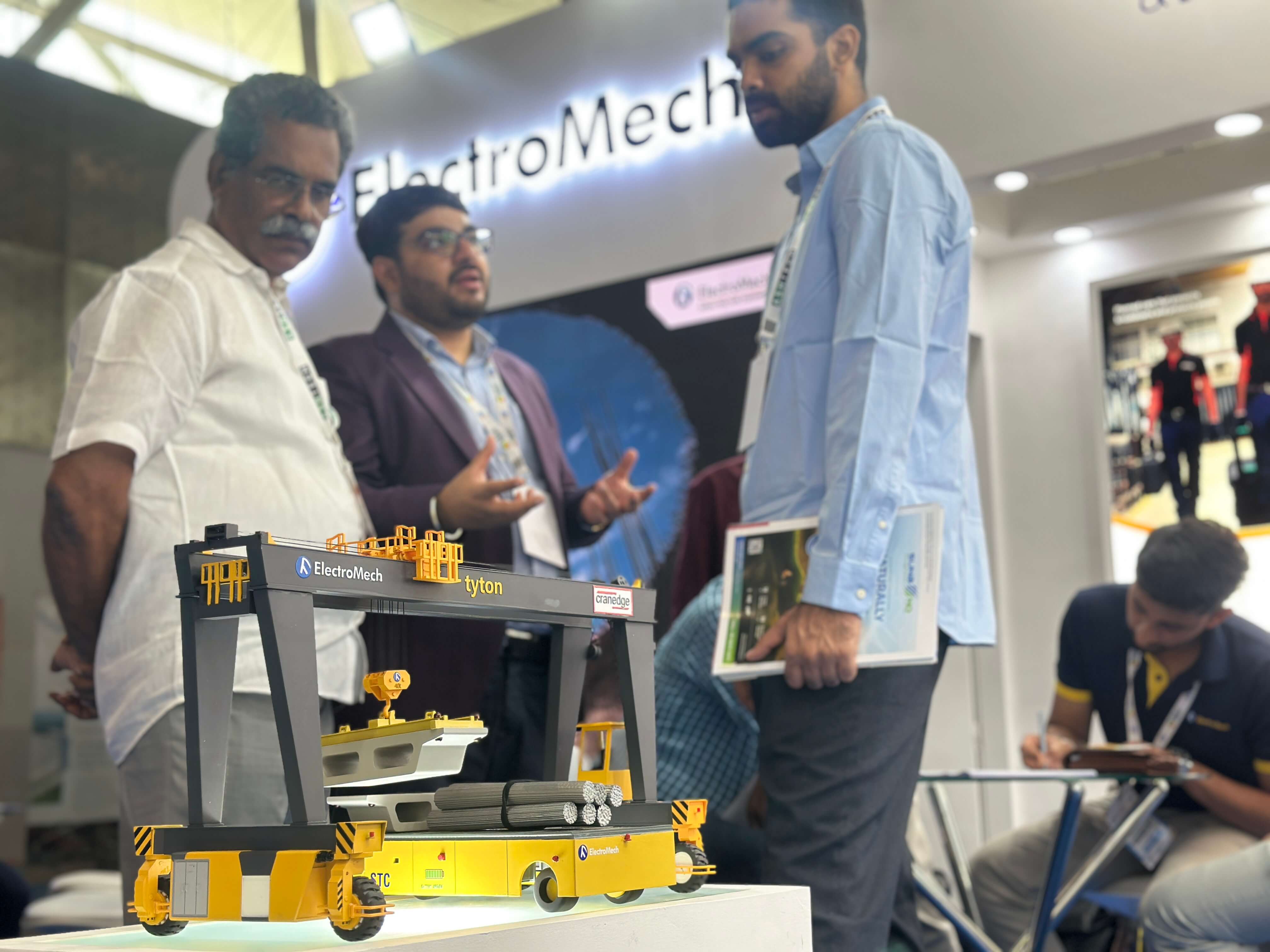
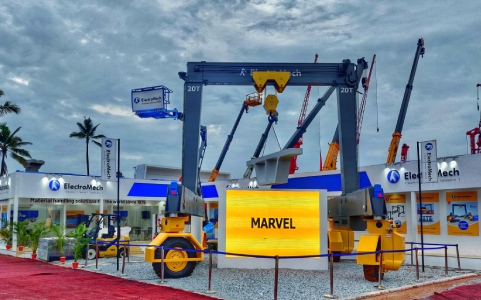
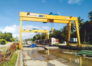
A Rubber Tyred Gantry Crane, or RTG, is a tyre-mounted gantry crane that can be easily moved across large outdoor yards, workshops, or factories. Being
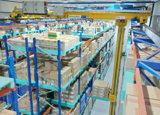
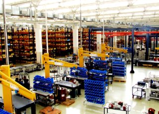
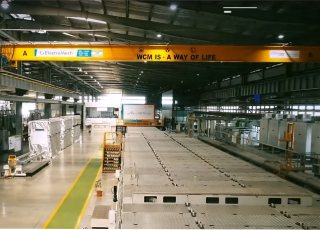
At present, optimum utilization of space by value and floor area is critical whether it is your warehouse or a
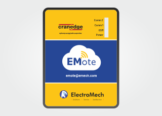
Effective use of the industrial internet helps you to connect to all the information about the EOT Cranes through a
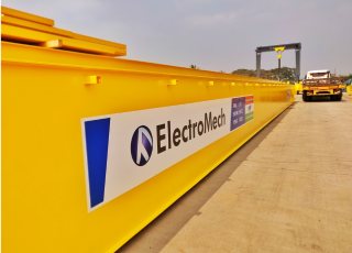
Commissioning an overhead crane is a significant investment; hence, you must decide wisely. Apart from finding the right equipment for
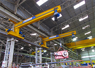
A wall travelling crane increases your facility productivity by quickly moving loads in a lateral movement without occupying much floor
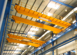
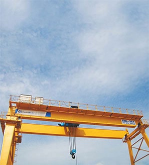
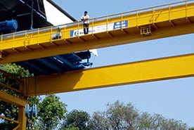
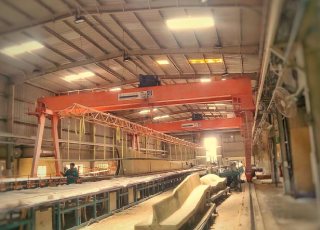
Cranes are the most critical equipment when it comes to material handling. Overhead and Gantry cranes are often considered the
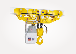
A hoist is the most important tool used in handling, lifting, loading, unloading and moving heavy objects in different industries,
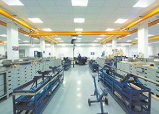
Have you seen X-Y rails with a light duty chain hoist hanging below them? This is how they look The
So, this blog is all about lifting beams! Why exactly do we need lifting beams for? What are the benefits

The wheel – one of the finest inventions by man. The wheel has evolved since its invention in 3500 B.C. and
What if we told you a single person can move up to 100t on his own! Baffled? Well it’s the
The demand for energy, globally, is going upwards year on year. To cater to global energy demands, the renewable energy
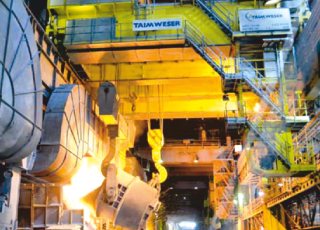
Material handling in steel industry is all about lifting heavy loads and handling hot liquid metals. The material handling equipment used in
Material Handling Equipment is an important part of any large industry and their various processes. However, when we deal with
As competitiveness increases companies in order to gain market share are hunting for solutions that help them achieve their objectives
Safe and efficient handling of heavy, delicate and over-sized pieces of glass is of utmost importance for glass manufacturing companies.
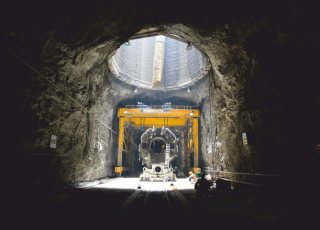
Growth in infrastructure sector has tremendous benefits on the economy of the country. Also, building a sustainable infrastructure for better
 India
India
 Indonesia
 Saudi Arabia
 Middle East